During the summer of 2002, Robert Balog designed new FET Control Boxes for laboratory use, with the assistence Andrew Niemerg (BSEE ’02), Brian Raczkowski (BSEE ’03, MSEE), and Nathan Brown (BSEE ’04). After successful roll-out for the Fall 2002 semster, the power handling capacity of the box was increased during the summer of 2003. The primary end application is ECE469, Power Electronics Lab, a senior-level lab course at the University of Illinois at Urbana-Champaign. Additionally, it was desired to support features used in research, and to have precision appropriate for research. It was supported in part by the Department of Electrical and Computer Engineering and in part by the Grainger Center for Electric Machinery and Electromechanics.
SPECIFICATIONS:
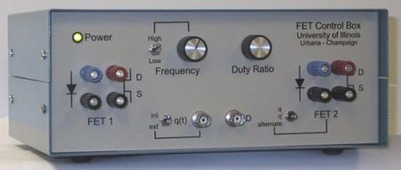
The equipment contain two pairs of FETs (IRFP360) and Diodes (MUR3040PT) and is conservatively rated for 10A continuous FET current. The uncommitted drain, source, anode and cathode terminals are available to the user via front panel mounted multi-way binding posts. The gate drive for each FET is independently isolated, allowing each FET to be used in either a high-side or low-side application.
Control power for the FET Control Box is either 120 Vac, 60Hz supplied through a standard IEC style ac inlet with integrated fuse, or 12-19 Vdc supplied via a 0.100″ coaxial barrel connector. A line frequency transformer provides galvanic isolation and control inputs are earth ground referenced for safety. A high frequency flyback power supply provides independently isolated voltages for the each FET gate drive.
The control circuit provides the user with direct frequency and duty ratio control of a PWM process via front-panel mounted knobs. Additionally, front-panel mounted BNC jacks allow the user to override these controls with either a switching function (square pulse train) via q (t) or a duty ratio modulating signal on D(t). The D(t) input is inverted allowing for implementation of a negative feedback control loop.
A front-panel mounted mode switch selects the way that the two FETs are switched:
| mode | Method of FET control |
| q | Identical Gate Drives |
| q’ | Complementary with Dead-time |
| Alternate | Alternating Pulses |
These three control modes allow one of many dc-dc, dc-ac, and ac-ac converter topologies with one or two controlled switches to be realized. Additionally, the q (t) BNC connectors allow multiple FET Control Boxes to be ganged together in Master / Slave arraignment to realize four switch converter topologies such as a full bridge dc-ac inverter or a universal frequency changer ac-ac converter.
DESIGN DETAILS:
Complete design data is available. Schematic and board layout was performed using the OrCAD suite from Cadence, PSD 14.0. Mechanical design was done in Microsoft Viso 2000. The design documentation is available in PDF format on this webpage. The estimated material cost of each box is $340. Most components were obtained through Newark or Allied, or when possible directly from stock in ECE Stores. Custom boxes with silkscreening came direct from Hammond. Heat sinks are custom from Aavid Thermalloy with machining done by the ECE Machine Shop. The bulk of the PCB and final assembly was performed by the Electronics Shop.